

Concealed fan coil unit
A concealed water-system terminal for individual room cooling and heating.
Concealed fan coil unit
Overview
The concealed fan coil unit is a water-system terminal for room cooling, dehumidification and heating. Installed above a suspended ceiling, it delivers conditioned air through a selected outlet and keeps the main equipment out of sight. Its low-profile arrangement suits interiors where the air-conditioning system needs to work with the ceiling design.
A centrifugal fan moves room air across a copper-tube, aluminium-fin coil. Chilled water removes heat during cooling operation, while hot water provides heating in the appropriate season. The unit works as part of a central water system rather than as a self-contained refrigeration appliance.
Return-air arrangement, connection side and available external static pressure can be coordinated with the room layout. Space for filter cleaning, coil inspection and condensate drainage should be included in the ceiling design.
PRODUCT DETAILS
Product Features
Low-profile concealed installation
The RNFP-WA arrangement fits within a ceiling void, leaving only the selected supply and return openings visible in the room. It supports a coordinated interior finish without a floor-standing cabinet.
Copper-tube heat exchanger
Seamless copper tubes and mechanically expanded aluminium fins form the coil assembly. Close contact between the tubes and fins supports heat transfer for both chilled-water cooling and hot-water heating.
Centrifugal air delivery
The fan and scroll assembly provide room-air circulation through the coil and connected outlets. Fan selection and operating speed are matched to the required airflow and the resistance of the duct route.
Return-air layout options
The catalogue identifies bottom-return and rear-return arrangements when a return-air box is selected. The return route should be agreed before ordering so that ceiling access and ductwork remain practical.
Static-pressure choices
Low- and higher-static-pressure versions allow the terminal to be selected for different duct and outlet arrangements. The appropriate version depends on the actual resistance, rather than simply choosing the largest motor.
Serviceable water connections
Left- or right-hand water connections can be specified to suit pipe routing. Pressure-checked coils, accessible filters and correctly arranged drain connections support installation, routine cleaning and seasonal operation.
MODEL DATA
Technical Specifications
RNFP fan-coil family · concealed horizontal arrangement. Catalogue pages 47–48, 49–50, 51–52.
Swipe tables horizontally to view all specifications.
| Model family | Airflow H / M / L (m³/h) | Cooling, H (kW) | Heating, H (kW) | Water flow (kg/h) |
|---|---|---|---|---|
| RNFP-34 | 340 / 260 / 170 | 1.8 | 2.7 | 319 |
| RNFP-51 | 510 / 390 / 260 | 2.7 | 4.05 | 478 |
| RNFP-68 | 680 / 510 / 340 | 3.6 | 5.4 | 638 |
| RNFP-85 | 850 / 640 / 430 | 4.5 | 6.75 | 797 |
| RNFP-102 | 1020 / 770 / 510 | 5.4 | 8.1 | 956 |
| RNFP-136 | 1360 / 1020 / 680 | 7.2 | 10.8 | 1275 |
| RNFP-170 | 1700 / 1280 / 850 | 9 | 13.5 | 1594 |
| RNFP-204 | 2040 / 1530 / 1020 | 10.8 | 16.2 | 1913 |
| RNFP-238 | 2380 / 1790 / 1190 | 12.6 | 18.9 | 2232 |
| Model family | Power at 12 / 30 / 50 Pa (W) | Noise at 12 / 30 / 50 Pa, dB(A) | Supply |
|---|---|---|---|
| RNFP-34 | 36 / 43 / 48 | 37 / 40 / 42 | AC 220 V / 50 Hz |
| RNFP-51 | 50 / 57 / 64 | 39 / 42 / 44 | AC 220 V / 50 Hz |
| RNFP-68 | 60 / 70 / 81 | 41 / 44 / 46 | AC 220 V / 50 Hz |
| RNFP-85 | 74 / 84 / 97 | 43 / 46 / 47 | AC 220 V / 50 Hz |
| RNFP-102 | 93 / 105 / 114 | 45 / 47 / 49 | AC 220 V / 50 Hz |
| RNFP-136 | 130 / 151 / 169 | 46 / 48 / 50 | AC 220 V / 50 Hz |
| RNFP-170 | 147 / 169 / 204 | 48 / 50 / 52 | AC 220 V / 50 Hz |
| RNFP-204 | 183 / 206 / 243 | 50 / 52 / 54 | AC 220 V / 50 Hz |
| RNFP-238 | 221 / 245 / 291 | 52 / 54 / 56 | AC 220 V / 50 Hz |
| Model | A | B | C | Approx. weight (kg) |
|---|---|---|---|---|
| RNFP-34WA | 750 | 460 | 490 | 12 |
| RNFP-51WA | 850 | 580 | 610 | 15 |
| RNFP-68WA | 950 | 650 | 680 | 16 |
| RNFP-85WA | 1050 | 780 | 810 | 18 |
| RNFP-102WA | 1150 | 900 | 930 | 19 |
| RNFP-136WA | 1350 | 1100 | 1130 | 25 |
| RNFP-170WA | 1650 | 1360 | 1390 | 29 |
| RNFP-204WA | 1850 | 1560 | 1590 | 33 |
| RNFP-238WA | 2050 | 1760 | 1790 | 36 |
H / M / L = high / medium / low speed. Performance is the catalogue’s RNFP family data; cabinet form and selected coil arrangement must be confirmed for the chosen product. Cooling: entering air 27°C dry bulb / 19.5°C wet bulb, entering water 7°C with a 5°C rise. Heating: entering air 21°C and entering water 60°C. Power and noise values are at high speed. Dimension letters refer to the selected model’s catalogue drawing.
WHERE IT WORKS
Applications
Suitable for hotels, restaurants, offices and other multi-room buildings where individual spaces need water-based comfort cooling and heating. The concealed arrangement is useful when the equipment should remain above the finished ceiling.
Select the airflow, water temperatures, connection side, drain route and terminal static pressure together. A separate fresh-air system is needed where outdoor-air ventilation is part of the room brief.
Send Your Requirements →- Hotel guestrooms and suites with coordinated ceiling outlets.
- Private offices and meeting rooms requiring room-level temperature control.
- Restaurants and reception areas where floor space must remain clear.
- Commercial refurbishment with sufficient ceiling depth and maintenance access.


RELATED EQUIPMENT
More in This Product Family

Ceiling Exposed Fan Coil Unit
An FP-WM ceiling-mounted hydronic fan coil unit with an exposed cabinet for room cooling and heating.
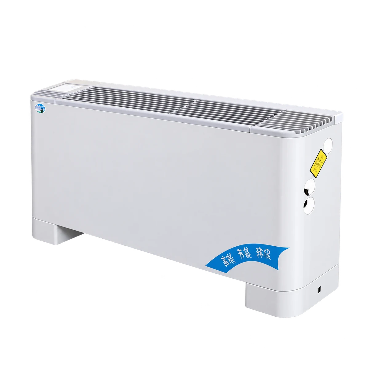
Vertical Surface Mounted Fan Coil Unit
A floor-standing water-system fan coil terminal with an exposed casing.

Card Type Fan Coil Unit
A ceiling cassette fan coil for room cooling and heating.
PROJECT INQUIRY
Discuss This Equipment
Tell us about your equipment requirements and installation conditions.
From cleaner air
to a better future.