
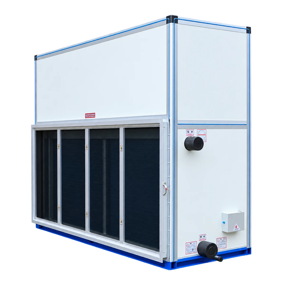
Vertical Air Handling Unit
Vertical air handling equipment for plant rooms and floor-standing installations.
Vertical Air Handling Unit
Overview
The vertical air handling unit is a floor-standing air-treatment assembly for plant rooms and other locations where an upright cabinet suits the available space. Its vertical arrangement brings the filter, water coil and fan sections together while leaving the connection layout to be coordinated with the duct network.
A centrifugal fan moves air through the selected filter and heat exchanger. Chilled water provides cooling and dehumidification, and an appropriate hot-water supply provides heating. The required coil rows and fan duty are selected against the actual design conditions.
The catalogue provides several vertical models and coil configurations. Final dimensions depend on the selected thermal duty and arrangement, so room height, access direction and the available space for servicing are considered before the layout is fixed.
PRODUCT DETAILS
Product Features
Upright floor-standing cabinet
The vertical form suits equipment areas with usable height and a limited plan arrangement. The cabinet position is coordinated with the building structure, pipe routing and duct connections.
Integrated air-treatment assembly
Filter, coil and fan sections form a central treatment path. This gives the designer one coordinated unit for the required air quantity and thermal duty.
Copper-tube water coil
The selected water coil exchanges heat between the building’s water circuit and the airstream. Catalogue coil arrangements allow duty to be reviewed for both conditioned-air and outdoor-air operation.
Centrifugal fan selection
The fan is chosen for the required airflow and the resistance of the downstream system. The pressure allowance includes filters, ducts, outlets and other selected accessories.
Insulation and drainage planning
An insulated cabinet and correctly arranged condensate disposal support cooling operation. A suitable drain trap, water-pipe insulation and protected connections form part of the installation.
Accessible inspection and cleaning
Filters and heat-transfer surfaces need periodic attention. The layout should leave practical access to the service side and avoid making the fan or coil inaccessible after the ductwork is installed.
MODEL DATA
Technical Specifications
RNJK-L vertical water-coil AHU · six-row coil catalogue data. Catalogue pages 21–22.
Swipe tables horizontally to view all specifications.
| Model reference | Airflow (m³/h) | External pressure (Pa) | Fan power (kW) | Noise dB(A) | Weight (kg) |
|---|---|---|---|---|---|
| 020L | 2000 | 160 | 0.45 | ≤60 | 110 |
| 030L | 3000 | 160 | 0.55 | ≤60 | 127 |
| 040L | 4000 | 210 | 0.75 | ≤62 | 146 |
| 050L | 5000 | 210 | 1.1 | ≤64 | 168 |
| 060L | 6000 | 210 | 1.5 | ≤64 | 193 |
| 070L | 7000 | 210 | 1.8 | ≤65 | 222 |
| 080L | 8000 | 210 | 2.2 | ≤66 | 255 |
| 0100L | 10000 | 260 | 2.2 | ≤66 | 294 |
| 0120L | 12000 | 260 | 3 | ≤67 | 338 |
| 0150L | 15000 | 260 | 4 | ≤68 | 390 |
| 0180L | 18000 | 260 | 2.2 × 2 | ≤68 | 468 |
| 0200L | 20000 | 310 | 3 × 2 | ≤69 | 560 |
| 0220L | 22000 | 310 | 3 × 2 | ≤70 | 672 |
| 0250L | 25000 | 460 | 4 × 2 | ≤71 | 806 |
| 0270L | 27000 | 460 | 4 × 2 | ≤72 | 967 |
| 0300L | 30000 | 460 | 5.5 × 2 | ≤73 | 1160 |
| 0350L | 35000 | 460 | 5.5 × 2 | ≤74 | 1390 |
| 0400L | 40000 | 460 | 7.5 × 2 | ≤75 | 1530 |
| 0450L | 45000 | 460 | 11 × 2 | ≤76 | 1836 |
| 0500L | 50000 | 560 | 15 × 2 | ≤77 | 2020 |
| 0600L | 60000 | 560 | 15 × 2 | ≤78 | 2120 |
| Model reference | Cooling, A/C duty (kW) | Cooling, fresh-air duty (kW) | Heating, A/C duty (kW) | Heating, fresh-air duty (kW) |
|---|---|---|---|---|
| 020L | 14.15 | 28.02 | 20.27 | 40.14 |
| 030L | 19.16 | 36.88 | 29.05 | 55.92 |
| 040L | – | 56.71 | 41.42 | 79.72 |
| 050L | 34.63 | 66.66 | 48.27 | 92.91 |
| 060L | 41.64 | 78.23 | 59.59 | 111.95 |
| 070L | 49.78 | 95.82 | 71.12 | 136.89 |
| 080L | 58.96 | 113.5 | 82.84 | 159.47 |
| 0100L | 75.97 | 146.23 | 105.72 | 203.5 |
| 0120L | 94.43 | 181.78 | 130.06 | 250.37 |
| 0150L | 119.62 | 230.26 | 164.37 | 316.41 |
| 0180L | 138.98 | 267.65 | 183.62 | 353.63 |
| 0200L | 145.44 | 279.13 | 203.12 | 389.81 |
| 0220L | 156.28 | 300.85 | 223.38 | 430.02 |
| 0250L | 180.48 | 347.42 | 254.97 | 490.82 |
| 0270L | 198.47 | 411.75 | 279.37 | 579.58 |
| 0300L | 225.23 | 433.57 | 315.41 | 607.17 |
| 0350L | 271.01 | 521.68 | 375.82 | 723.42 |
| 0400L | 316.49 | 609.24 | 437.23 | 841.65 |
| 0450L | 355.34 | 683.38 | 490.4 | 943.12 |
| 0500L | 396.09 | 762.3 | 546.52 | 1054.82 |
| 0600L | 478.71 | 920.15 | 660.15 | 1268.91 |
The printed performance table covers vertical / horizontal arrangements; these references identify the vertical layout. A/C duty and all-fresh-air duty are different catalogue conditions. A dash in the 040L cooling cell indicates an ambiguous source value requiring confirmation. Confirm the complete model code, coil rows, water conditions and installation drawing.
WHERE IT WORKS
Applications
Suitable for commercial and industrial buildings using centralized chilled- or hot-water systems. The upright form is particularly relevant where an equipment room can accommodate the required cabinet height and floor loading.
Confirm airflow, pressure, water temperatures, cooling and heating duty, connection side and access space. The final unit dimensions follow the selected model and coil arrangement.
Send Your Requirements →- Office and commercial plant rooms with centralized ducted supply.
- Hotel or public-building air-conditioning systems.
- Industrial areas needing water-coil air treatment.
- Refurbishment where an upright equipment layout suits the available room.


RELATED EQUIPMENT
More in This Product Family

Ceiling-Mounted Heat Recovery Unit
A ceiling-mounted air handling unit combining fresh air treatment and heat recovery.
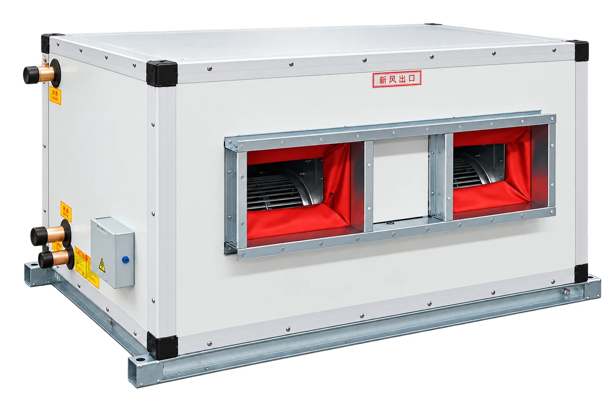
Ceiling-Mounted Fresh Air Handling Unit
Ceiling-mounted treatment and distribution of outdoor air.

Modular Air Handling Unit
Modular functional sections configured around the project air-treatment requirements.
PROJECT INQUIRY
Discuss This Equipment
Tell us about your equipment requirements and installation conditions.
From cleaner air
to a better future.