
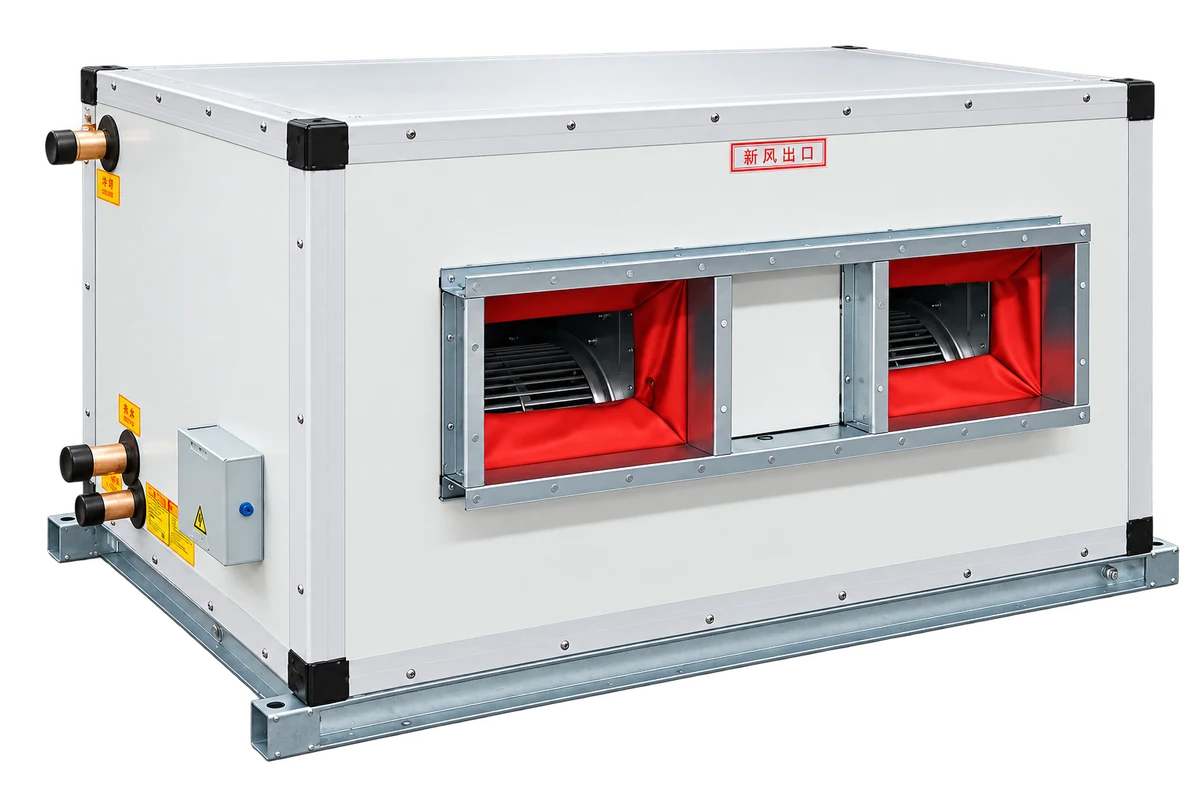
Установленный на потолке блок обработки свежего воздуха
Ceiling-mounted treatment and distribution of outdoor air.
Установленный на потолке блок обработки свежего воздуха
Overview
The ceiling-mounted fresh air handling unit treats and distributes outdoor air from within a suspended-ceiling installation. Its compact horizontal arrangement keeps the main equipment above the occupied room and connects to the building’s ductwork, water circuit and drainage system.
A fan draws air through filtration and a water coil before it is supplied to the room network. The selected coil can cool and dehumidify incoming air or provide heating from hot water. This is an air-treatment terminal connected to external utilities, rather than a self-contained cooling plant.
The D-series catalogue includes several airflow sizes and coil arrangements. Selection considers the outdoor-air duty, duct resistance and ceiling depth together, with clear access to the filter, fan, coil and condensate connection.
PRODUCT DETAILS
Product Features
Ceiling-mounted space use
The horizontal cabinet is suspended above the finished ceiling, reducing the amount of equipment occupying floor space. Ceiling structure and support points are checked for the selected unit.
Filtered outdoor-air treatment
A filter section removes incoming particulate contamination before the selected thermal treatment stages. The filter arrangement is coordinated with both air-quality needs and the available fan pressure.
Cooling and heating coils
Water-coil configurations are selected to meet the project duty. Cooling operation can also remove moisture when the coil conditions are suitable, with condensate collected and drained.
Ducted air distribution
The fan supplies air through connected ducts and room outlets. Airflow and external static pressure are chosen from the real system resistance rather than the nominal airflow alone.
Compact insulated construction
The ceiling series uses an integrated cabinet arrangement intended for concealed service spaces. Insulation and connection details are coordinated to limit unwanted heat exchange and surface condensation.
Practical installation access
The installation needs a level support arrangement, suitable condensate fall and a drain trap where required. Flexible connections and clear maintenance openings help prevent service loads from being carried by the casing.
MODEL DATA
Technical Specifications
RNJK-D ceiling air-handling series · four-row coil catalogue data. Catalogue pages 17–18.
Swipe tables horizontally to view all specifications.
| Model reference | Airflow (m³/h) | External pressure (Pa) | Fan power (kW) | Noise dB(A) | Weight (kg) |
|---|---|---|---|---|---|
| 010D | 1000 | 150 | 0.25 | ≤58 | 62 |
| 010×2D | 2000 | 150 | 0.25 × 2 | ≤60 | 86 |
| 015D | 1500 | 210 | 0.37 | ≤59 | 72 |
| 015×2D | 3000 | 210 | 0.37 × 2 | ≤61 | 107 |
| 020D | 2000 | 230 | 0.45 | ≤60 | 84 |
| 020×2D | 4000 | 230 | 0.45 × 2 | ≤62 | 128 |
| 025D | 2500 | 250 | 0.45 | ≤61 | 91 |
| 025×2D | 5000 | 250 | 0.45 × 2 | ≤63 | 149 |
| 030D | 3000 | 290 | 0.75 | ≤62 | 98 |
| 030×2D | 6000 | 290 | 0.75 × 2 | ≤64 | 167 |
| 035D | 3500 | 270 | 0.8 | ≤62 | 119 |
| 035×2D | 7000 | 270 | 0.8 × 2 | ≤64 | 195 |
| 040D | 4000 | 300 | 1.1 | ≤63 | 134 |
| 040×2D | 8000 | 300 | 1.1 × 2 | ≤65 | 224 |
| 050D | 5000 | 320 | 1.5 | ≤64 | 154 |
| 050×2D | 10000 | 320 | 1.5 × 2 | ≤66 | 240 |
| 060D | 6000 | 390 | 1.8 | ≤64 | 177 |
| 060×2D | 12000 | 390 | 1.8 × 2 | ≤66 | 320 |
| 070D | 7000 | 390 | 1.8 | ≤65 | 204 |
| 070×2D | 14000 | 390 | 1.8 × 2 | ≤67 | 370 |
| 080D | 8000 | 440 | 2.2 | ≤66 | 234 |
| 080×2D | 16000 | 440 | 2.2 × 2 | ≤68 | 425 |
| Model reference | Cooling, A/C duty (kW) | Cooling, fresh-air duty (kW) | Heating, A/C duty (kW) | Heating, fresh-air duty (kW) |
|---|---|---|---|---|
| 010D | 5.61 | 10.26 | 10.64 | 19.46 |
| 010×2D | 11.33 | 20.62 | 21.28 | 38.72 |
| 015D | 8.58 | 15.98 | 15.68 | 29.21 |
| 015×2D | 17.16 | 31.59 | 31.5 | 57.98 |
| 020D | 11.88 | 21.74 | 21 | 38.43 |
| 020×2D | 21.8 | 44.41 | 39.8 | 77.78 |
| 025D | 14.41 | 26.52 | 24.92 | 45.87 |
| 025×2D | 28.93 | 53.25 | 49.84 | 91.74 |
| 030D | 18.59 | 34.01 | 30.94 | 56.61 |
| 030×2D | 37.29 | 68.65 | 61.88 | 113.92 |
| 035D | 20.79 | 38.04 | 35.28 | 64.55 |
| 035×2D | 41.58 | 76.09 | 70.56 | 129.12 |
| 040D | 23.76 | 44.01 | 40.32 | 74.68 |
| 040×2D | 47.52 | 87.49 | 80.64 | 148.46 |
| 050D | 28.16 | 50.83 | 49.28 | 88.94 |
| 050×2D | 58.52 | 101.48 | 93.24 | 161.69 |
| 060D | 34.32 | 63.18 | 62.83 | 115.67 |
| 060×2D | 67.76 | 110.21 | 122.64 | 199.48 |
| 070D | 39.49 | 72.26 | 69.41 | 127.01 |
| 070×2D | 79.99 | 152.54 | 153.48 | 292.67 |
| 080D | 46.53 | 85.14 | 81.68 | 149.46 |
| 080×2D | 91.08 | 176.86 | 160.02 | 310.73 |
Model references follow the catalogue’s suspended ceiling arrangement. A/C duty and all-fresh-air duty use different operating conditions. Confirm the complete model, coil rows, water conditions, ceiling load and access requirements when selecting the unit.
WHERE IT WORKS
Applications
Suitable for offices, hotels, shops and other buildings where outdoor air needs treatment but floor-standing plant space is limited. It can serve a defined room group or ventilation zone through the selected duct layout.
Confirm ceiling clearance, lifting and service access, water duty, air resistance and drainage before ordering. Any electric heating, motor control or damper options are confirmed for the selected configuration.
Send Your Requirements →- Commercial ceiling voids with adequate depth and structural support.
- Hotel corridors or service areas distributing treated fresh air.
- Office and retail zones supplied through short or medium duct routes.
- Renovation projects with accessible water and condensate connections.

RELATED EQUIPMENT
More in This Product Family

Установленный на потолке блок рекуперации тепла
A ceiling-mounted air handling unit combining fresh air treatment and heat recovery.
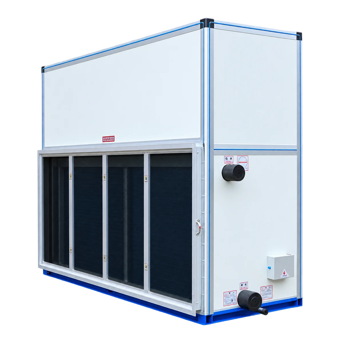
Вертикальный блок обработки воздуха
Vertical air handling equipment for plant rooms and floor-standing installations.

Модульный блок обработки воздуха
Modular functional sections configured around the project air-treatment requirements.
PROJECT INQUIRY
Discuss This Equipment
Tell us about your equipment requirements and installation conditions.
From cleaner air
to a better future.