

Ceiling-Mounted Heat Recovery Unit
A ceiling-mounted air handling unit combining fresh air treatment and heat recovery.
Ceiling-Mounted Heat Recovery Unit
Overview
The ceiling-mounted heat recovery unit combines ventilation-air treatment and energy exchange in a suspended air-handling format. It is intended for projects that need both supply and extract functions but cannot allocate the floor space required by a larger plant-room unit.
The selected recovery section transfers useful energy between incoming outdoor air and outgoing air. Additional filter, coil and moisture-treatment sections can be arranged around this function, depending on the selected configuration and the required leaving-air condition.
The catalogue’s suspended recovery air-handler arrangement differs from a simple room fan: fan pressure, thermal duty, air paths and service clearances are selected together. Water connections, condensate disposal and any humidification utilities are included only where the selected treatment stages require them.
PRODUCT DETAILS
Product Features
Suspended equipment arrangement
The cabinet is designed to make use of an overhead service zone. Structural supports, handling access and available ceiling depth must suit the selected unit and its operating weight.
Integrated energy exchange
The recovery function uses the difference between extract and outdoor-air conditions. The actual exchange method and recovery behaviour are confirmed for the selected unit arrangement.
Separate supply and extract duties
The catalogue provides distinct supply and extract fan duties. Both air paths are considered when calculating airflow, duct resistance and the intended ventilation balance.
Optional thermal treatment
Cooling and heating coils can be included in the selected air-treatment arrangement. Their capacity and water conditions are coordinated with the ventilation load and the room requirements.
Filtration and moisture options
Filter stages and any humidification section are chosen for the application. These functions are not assumed to be the same on every ceiling recovery unit.
Serviceable installation planning
The suspended position needs practical access for filters, fans, recovery components and drains. Maintenance openings and clearance should be agreed before the finished ceiling is installed.
MODEL DATA
Technical Specifications
RNJK-R suspended ceiling heat-recovery AHU. Catalogue pages 15–16.
Swipe tables horizontally to view all specifications.
| Model | Airflow (m³/h) | Supply fan (kW) | Supply external pressure (Pa) | Extract fan (kW) | Extract external pressure (Pa) | Humidification (kg/h) |
|---|---|---|---|---|---|---|
| RNJK-010R | 1000 | 0.45 | 150 | 0.2 | 180 | 3 |
| RNJK-013R | 1300 | 0.45 | 150 | 0.2 | 180 | 3.3 |
| RNJK-015R | 1500 | 0.45 | 145 | 0.2 | 180 | 4.1 |
| RNJK-018R | 1800 | 0.55 | 210 | 0.45 | 210 | 5.2 |
| RNJK-020R | 2000 | 0.55 | 210 | 0.45 | 210 | 5.7 |
| RNJK-024R (2400) | 2400 | 0.55 | 200 | 0.45 | 210 | 7.2 |
| RNJK-024R (2500) | 2500 | 0.7 | 290 | 0.55 | 274 | 8.6 |
| RNJK-030R | 3000 | 0.7 | 260 | 0.55 | 250 | 8.6 |
| RNJK-035R | 3500 | 1.1 | 210 | 0.75 | 270 | 11 |
| RNJK-040R | 4000 | 1.1 | 180 | 0.75 | 230 | 12 |
| RNJK-045R | 4500 | 1.5 | 250 | 1 | 270 | 12 |
| RNJK-050R | 5000 | 1.5 | 210 | 1 | 270 | 12.6 |
| RNJK-060R | 6000 | 1.8 | 350 | 2.2 | 230 | 21.9 |
| RNJK-080R | 8000 | 3.4 | 300 | 2.2 | 230 | 28.5 |
| RNJK-0100R | 10000 | 4 | 500 | 3.5 | 400 | 28 |
| Model | L × W × H (mm) |
|---|---|
| RNJK-010R | 2020 × 1100 × 615 |
| RNJK-013R | 2020 × 1100 × 615 |
| RNJK-015R | 2020 × 1100 × 615 |
| RNJK-018R | 2215 × 1305 × 615 |
| RNJK-020R | 2215 × 1305 × 615 |
| RNJK-024R (2400) | 2215 × 1305 × 615 |
| RNJK-024R (2500) | 2215 × 1400 × 715 |
| RNJK-030R | 2215 × 1400 × 715 |
| RNJK-035R | 2300 × 1500 × 715 |
| RNJK-040R | 2300 × 1500 × 715 |
| RNJK-045R | 2400 × 1600 × 735 |
| RNJK-050R | 2400 × 1600 × 735 |
| RNJK-060R | 2500 × 1650 × 815 |
| RNJK-080R | 2950 × 2150 × 900 |
| RNJK-0100R | 2950 × 2150 × 900 |
Supply and extract fan ratings are separate. Humidification is the catalogue’s configured value, not a requirement for every order. The source prints RNJK-024R for both 2,400 and 2,500 m³/h entries; airflow is appended here to distinguish them without inventing a corrected code. Confirm coil rows and final dimensional drawing.
WHERE IT WORKS
Applications
Suitable for commercial projects requiring a suspended recovery air handler and a defined duct network. The layout is relevant when useful extract air is available and ceiling or overhead service space can accommodate the complete selected assembly.
Confirm air quantities, recovery type, thermal duties, utilities and external static pressure. Review ceiling support, connection routing and maintenance access alongside the unit dimensions.
Send Your Requirements →- Offices and shared commercial areas with overhead service zones.
- Hotel ventilation serving a group of occupied rooms.
- Public-building fresh-air systems with selected thermal treatment.
- Refurbishment where floor space is limited but overhead access is practical.


RELATED EQUIPMENT
More in This Product Family
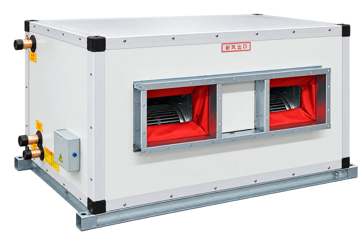
Ceiling-Mounted Fresh Air Handling Unit
Ceiling-mounted treatment and distribution of outdoor air.
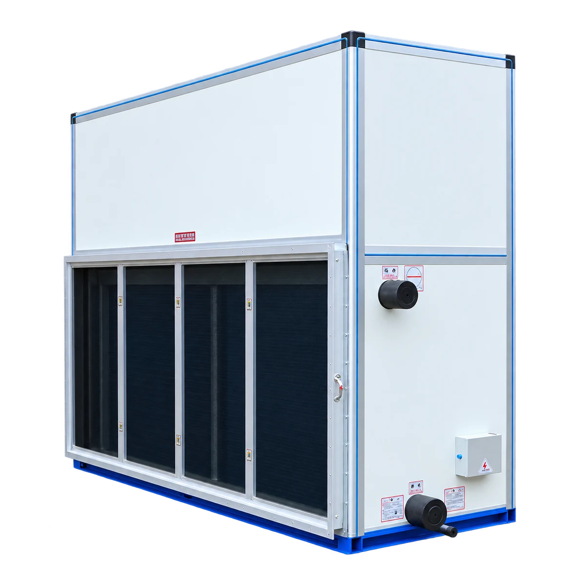
Vertical Air Handling Unit
Vertical air handling equipment for plant rooms and floor-standing installations.

Modular Air Handling Unit
Modular functional sections configured around the project air-treatment requirements.
PROJECT INQUIRY
Discuss This Equipment
Tell us about your equipment requirements and installation conditions.
From cleaner air
to a better future.